Showing posts with label dual vvt-i. Show all posts

Toyota Vitz

The Toyota Vitz a 3 and 5-door hatchback (sold in different markets as the Toyota Yarisand formerly as the Toyota Echo) is a line of subcompact cars first launched by Toyota in 1999, designed by Sotiris Kovos. In Europe, the Americas, Australia, New Zealand andSouth Africa, the Vitz is sold as the Yaris Liftback (or simply Yaris).

The first generation Vitz was known as the Echo Hatchback in Canada, Hong Kong, Australia, New Zealand and in the United States. In its second generation, the Vitz and Belta are marketed in US/Canada as the Yaris Hatchback and Yaris, respectively.
First generation (1999-2005)


Europe/Israel :-

                               The Toyota Yaris went on sale in Europe and Israel early in 1999. After the launch of the European Yaris hatchback in May 1999, a slightly modified version went on sale in Canada for the 2004 model year as the Echo hatchback, but not in the United States, where theToyota Echo sedan and coupe were the lone models. The Toyota Yaris was votedEuropean Car of the Year in 2000, defeating the innovative Fiat Multipla and Opel/Vauxhall Zafira by a narrow and large margin. The Yaris was also awarded the 2000 Semperit Irish Car of the Year.
File:2003-2005 Toyota Echo (NCP13R MY03) Sportivo 3-door hatchback 01.jpg


Instead of conventional instruments, the Yaris and Echo hatchbacks utilized digital instruments which were mounted in a "pod" in the center of the dashboard. The Canadian Echo hatchback (and the Yaris T Sport) had a conventional speedometer but it was still mounted in the center of the dashboard.

The European Yaris was initially available withpetrol-powered 4-cylinder 1.0 L or 1.3 L engines with Toyota's VVT-i technology, with the warm hatch 1.5 L T Sport following in 2001. After the 2003 facelift, a 1.4 L D4-D diesel engine offering 75 hp (56 kW) was also included in the lineup. This diesel engine is also licensed to BMWfor use in their MINI One D model. The use of sophisticated engine management systems was said to give the equivalent of 1.4 litre performance from a 1.0 litre engine while maintaining low fuel consumption and emissions.


On most European and Israeli markets, the Yaris was a stronger seller than the Starlet that it replaced.


Japan

The Japanese Vitz RS (European Yaris T-Sport) was introduced in 2001 and was powered by a 1.5 L (108 hp) engine, shared with the Echo, Vios, as well as the Scion xA. The 1.5 L T Sport was more fun to drive than the base models because of a sportier suspension and extra power compared to the 1.3 L (90 hp) and 1.0 L (67 hp) models. Later, the Vitz RS was modified by TRD (Toyota Racing Developments), and was fitted with a turbo-charger. A limited run was produced with a power output of around 120 kW (163 PS; 161 bhp) and a 0–100 km/h (0-62 mph) time of just 7 seconds. Note that there is also a 1.3L JDM Vitz RS with the 2NZ-FE engine 7–10 km/litre in city 12–13 km/litre which shares brakes, body kit, headlights, suspension and interior with the 1.5 L Vitz RS 5.5-9.5 km/litre in city 10-12.8 km/litre on highway.


North America

                                The Echo sold in very high volumes in Canada, where smaller cars are much more popular than in the US. Sales were so high that Toyota introduced the 3 and 5-door hatchback models to the Canadian Toyota lineup for the 2004 model year. They were sold as the 'Echo hatchback' and look almost identical to the European Yaris, but with minor changes (e.g. larger bumpers) to meet Canadian safety requirements.

File:'04-'05 Toyota Echo 3-Door (Orange Julep).JPG

Australia

                       The Echo was also very popular in Australia. First introduced in late 1999 to replace the aging Starlet, the Echo was available as a 3 or 5-door hatchback, fitted only with the 1.3l VVT-i engine. An Echo Sportivo variant, fitted with the 1.5l VVT-i engine, was made available for a limited time in Australia. The Sportivo was very similar to the European Yaris T-Sport.

File:2001 Toyota Vitz RS (NCP13).jpg

Yaris Verso

                          An unusual addition to the Yaris range came in late 1999 with the Yaris Verso, or Echo Verso in some markets, a small MPV which used the same running gear as the conventional hatchback, but was designed to have an even more practical interior.
In Japan, the model bore the name of 'Funcargo'. The model was replaced by the Ractis in 2004, but this is a Japan-only model due to the disappointing sales of the Yaris Verso in Europe.

File:Toyota Yaris Verso.jpg

Second generation (2005-present)
                                                            Toyota redesigned the Vitz in early 2005, going on sale in Japan that February. The Toyota Belta sedan, shares underpinnings with the Vitz. However, while the Vitz was designed at Toyota's European ED2 design studios, the Belta was designed at their Japanese design studios. While the outgoing Vitz hatchback and Platz sedan look and feel virtually alike, the redesigned Vitz and Belta are more subtly related. The two cars share a frame and the drivetrain components however the sheet metal is different.

The European, Australian, Canadian, Mexican, Venezuelan and Puerto Rican markets saw the second generation Vitz near the end of 2005. In the Australian and North American markets, the car was sold as the "Yaris" for the first time. The production Yaris for the US market was unveiled at the Los Angeles Auto Show in January 2006.

The new Yaris is built in Japan, France, and Thailand.

The previous 4-cylinder 1.0 VVT-i engine was replaced by the 3-cylinder engine also found in the Toyota Aygo. The 1.3 liter engine was revised to offer slightly more power, and the 1.4 D-4D got a 15 PS (11 kW; 15 hp) boost to 90 PS (66 kW; 89 hp), the former engine allowing it to achieve exceptional fuel economy. The Yaris became the first car in its class to offer nine airbags.

For model year 2007 on Japanese models only, G-BOOK, a subscription telematicsservice, is offered as an option.
I

t has continued to prove popular in Europe, particularly in Britain, where it competes with models such as the Ford Fiesta, Vauxhall Corsa, Citroen C2 and the Peugeot 207. It also has been very popular in Pakistan.

In January 2009, Toyota recalled 1.28 million vehicles worldwide based on the Yaris platform, such as the Vitz, Belta and the Ractis. The recall is based on a seat belt defect that, in severe front-end collisions, could cause a foam pad in the vehicle to ignite.
File:Toyota Yaris II Facelift Facelift 20090621 front.JPG

File:Toyota Yaris 3 door.jpg


North America


The Canadian Yaris hatchback is available in 3 and 5-door models, running on the Toyota NZ engine, a 1.5 L 4-cylinder VVT-i engine rated 106 bhp (79 kW) and 103 lb·ft (140 N·m). The 2006 Yaris with the 1.5 liter engine can achieve fuel economy ratings of 40 miles per US gallon (5.9 L/100 km; 48 mpg-imp) during highway driving and 34 mpg-US (6.9 L/100 km; 41 mpg-imp) during city driving. 3-door CE and 5-door LE versions come with 14 in (355.6 mm) wheels, while RS models are equipped with 15 in (381 mm) alloys with standard anti-lock braking system (ABS) and electronic brakeforce distribution (EBD). In addition, 2008 RS models include new front and back skirts.

The US Yaris is similar to the Canadian variant, and is the successor to the previous North American Toyota Echo. In the US, the 3-door Vitz shares the Yaris name with the Toyota Belta sedan. The 3-door model is called the 'Yaris Liftback', while the 5-door model will be sold starting with the 2009 model year in the United States and competes with the similarly-equipped Scion xD. The 2008 model year US Yaris comes standard with the 1.5 liter VVT-i engine producing 106 hp and 103 lb·ft and five-speed manual transmission C54, the four-speedautomatic U340E being optional. Fuel economy is rated at 29 mpg 7-9.5 km/lite in the city and 36 mpg 11-12.8 km/lite on the highway with the manual transmission. While front airbags are standard, as mandated by the law, ABS and side airbags are available only as an option.

In Canada, the CE, LE, and RS packages are replaced by the more modular convenience, power, and all-weather guard packages.

For the 2009 year, the Yaris 5-door liftbacks join the lineup of the existing 4-door sedans and 3-door liftbacks because of the increased demand for fuel efficient subcompact cars. In addition to the new 5-door liftback, all 2009 Yaris models come standard with anti-lock brakes (ABS), front seat-mounted side airbags and front and rear curtain side airbags. For 2009, Toyota also added cruise control as an option on liftback models, and has added a few more colour choices.

The Yaris has been praised by the automotive press for its extremely high fuel economy, but criticized for its excessive body roll (due to a soft suspension and high ride height) and the initial lack of a manual transmission on 5-door models.

The 2010 model has a 5-speed manual option for the 5-door. It also has the Star Safety System - Vehicle Stability Control (VSC) + Traction Control (TRAC), Anti-lock Brake System (ABS) with Electronic Brake-force Distribution (EBD) and Brake Assist.


Safety


2005 EuroNCAP crash test (5-door)
Adult: , 35 points
Child: , 34 points
Pedestrian: , 18 points

National Highway Traffic Safety Administration (NHTSA) crash test (5-door)
Frontal driver:
Frontal passenger:
Side driver (side airbags):
Side rear passenger (side airbags):
Rollover:

National Highway Traffic Safety Administration (NHTSA) crash test (3-door)
Frontal driver:
Frontal passenger:
Side driver: (no side airbags)
Side driver: (side airbags):[13]
Side rear passenger (with or without side airbag):
Rollover: 

Malaysia

The Yaris is also available in Malaysia, powered by the 1NZ-FE engine with 4-cylinder DOHC with VVT-i. It comes in 2 trim levels: 1.5 G and 1.5 S, both with 4-speed automatic transmission with Super ECT and Gate Shifter, featuring an output of 80 kW@6000 rpm, and a torque of 141 N·m (104 lb·ft)@4200 rpm.
The 1.5S variant comes with 15” solid disc brakes for the front wheels, front and rear bumper spoilers, side skirt and rear spoiler, amber Optitron meter, a black center cluster, with a steering wheel, gearshift and knob in leather.

Indonesia

The Yaris was launched in Indonesia in 2006. It is powered by the 1.5 liter 1NZ-FE engine matched to 4-speed super ECT automatic or 5-speed Manual transmission. Initially, the Yaris was offered in E, S, and S Limited trim levels. The manual only S and automatic only S Limited came with front, side and rear spoilers. The Yaris received minor changes for 2009 model year with new bumpers, grille, tail lights, and revised interior. The new base model J was added into the line up. The mid-level E got aero-style mudguards and roof spoiler, while full body kits are remained on the S and S Limited. The S Limited TRD Sportivo with extreme body kits and lowered springs was offered in the small numbers. Prepared by Toyota Team Indonesia, the slightly modified Yaris is raced in the Indonesian Touring Car Championship, and often achieved good results.

RS

The Toyota Yaris RS was launched in 2007. It was first seen at the Geneva Motor Show and is powered by the new 130 bhp (97 kW) 1.8 2ZR-FE DOHC L dual VVT-i I4 gasoline engine, which can reach 100 km/h (62 mph) in under 10 seconds. The RS features 17 in (431.8 mm) alloy wheels, a mesh grille, a redesigned rear bumper, deep side skirts and a tail spoiler. It also features redesigned headlights and taillights. As in the previous T-Sport, there are extra rear lights on the bumper. Essentially, it is a JDM Vitz RS fitted with a 2ZR-FE engine.

File:YarisNCP91EGrey.jpg


Hydraulic brake

The hydraulic brake is an arrangement of braking mechanism which uses brake fluid, typically containing ethylene glycol, to transfer pressure from the controlling unit, which is usually near the operator of the vehicle, to the actual brake mechanism, which is usually at or near the wheel of the vehicle.

File:Hydraylic disc brake diagram.jpg

Construction:- 
                                     The most common arrangement of hydraulic brakes for passenger vehicles, motorcycles, scooters, and mopeds, consists of the following:
Brake pedal or lever
A pushrod (also called an actuating rod)
A master cylinder assembly containing a piston assembly (made up of either one or two pistons, a return spring, a series of gaskets/ O-rings and a fluid reservoir)
Reinforced hydraulic lines
Brake caliper assembly usually consisting of one or two hollow aluminum or chrome-plated steel pistons (called caliper pistons), a set of thermally conductive brake pads and a rotor (also called a brake disc) or drum attached to a axle.

The system is usually filled with a glycol-ether based brake fluid (other fluids may also be used).

At one time, passenger vehicles commonly employed disc brakes on the front wheels and drum brakes on the rear wheels. However, because disc brakes have been shown a better stopping performance and are therefore generally safer and more effective than drum brakes, four-wheel disc brakes have become increasingly popular, replacing drums on all but the most basic vehicles. Many two-wheel vehicles designs, however, continue to employ a drum brake for the rear wheel.

For simplicity, the braking system described hereafter uses the terminology and configuration for a simple disc brake.

System Operation :-
                                                 Within a hydraulic brake system, as the brake pedal is pressed/ brake lever is squeezed, a pushrod exerts force on the piston(s) in the master cylinder causing fluid from the brake fluid reservoir to flow into a pressure chamber through a compensating port which results in an increase in the pressure of the entire hydraulic system. This forces fluid through the hydraulic lines toward one or more calipers where it acts upon one or two additional caliper pistons secured by one or more seated O-rings which prevent the escape of any fluid from around the piston.

The brake caliper piston(s) then apply force to the brake pads. This causes them to be pushed against the spinning rotor, and the friction between the pads and the rotor causes a braking torque to be generated, slowing the vehicle. Heat generated from this friction is often dissipated through vents and channels in the rotor and through the pads themselves which are made of specialized heat-tolerant materials (kevlar, sintered glass, et al.).

Subsequent release of the brake pedal/ lever allows the spring(s) within the master cylinder assembly to return that assembly's piston(s) back into position. This relieves the hydraulic pressure on the caliper allowing the brake piston in the caliper assembly to slide back into its housing and the brake pads to release the rotor. Unless there is a leak somewhere in the system, at no point does any of the brake fluid enter or leave.

Component specifics :-
                                        (For typical light duty automotive braking systems)

The brake pedal is a simple lever. One end is attached to the framework of the vehicle, a pushrod extends from a point along its length, and the foot pad is at the other end of the lever. The rod either extends to the master cylinder (manual brakes) or to the vacuum booster (power brakes).

In a four-wheel car, the master cylinder is divided internally into two sections, each of which pressurizes a separate hydraulic circuit. Each section supplies pressure to one circuit. Passenger vehicles typically have either a front/rear split brake system or a diagonal split brake system (the master cylinder in a motorcycle or scooter may only pressurize a single unit, which will be the front brake).

A front/rear split system uses one master cylinder section to pressurize the front caliper pistons and the other section to pressurize the rear caliper pistons. A split circuit braking system is now required by law in most countries for safety reasons; if one circuit fails, the other circuit can stop the vehicle.

Diagonal split systems were used initially on American Motors automobiles in the 1967 production year. The right front and left rear are served by one actuating piston while the left front and the right rear are served, exclusively, by a second actuating piston (both pistons pressurize their respective coupled lines from a single foot pedal). If either circuit fails, the other, with at least one front wheel braking (the front brakes provide most of the speed reduction) remains intact to stop the mechanically-damaged vehicle. Just before 1970, diagonally split systems had become universal for automobiles sold in the United States.

The diameter and length of the master cylinder has a significant effect on the performance of the brake system. A larger diameter master cylinder delivers more hydraulic fluid to the caliper pistons, yet requires more brake pedal force and less brake pedal stroke to achieve a given deceleration. A smaller diameter master cylinder has the opposite effect.

A master cylinder may also use differing diameters between the two sections to allow for increased fluid volume to one set of caliper pistons or the other.


Power brakes:-

                                        The vacuum booster or vacuum servo is used in most modern hydraulic brake systems which contain four wheels. The vacuum booster is attached between the master cylinder and the brake pedal and multiplies the braking force applied by the driver. These units consist of a hollow housing with a movable rubber diaphragm across the center, creating two chambers. When attached to the low-pressure portion of the throttle body or intake manifold of the engine, the pressure in both chambers of the unit is lowered. The equilibrium created by the low pressure in both chambers keeps the diaphragm from moving until the brake pedal is depressed. A return spring keeps the diaphragm in the starting position until the brake pedal is applied. When the brake pedal is applied, the movement opens an air valve which lets in atmospheric pressure air to one chamber of the booster. Since the pressure becomes higher in one chamber, the diaphragm moves toward the lower pressure chamber with a force created by the area of the diaphragm and the differential pressure. This force, in addition to the driver's foot force, pushes on the master cylinder piston. A relatively small diameter booster unit is required; for a very conservative 50% manifold vacuum, an assisting force of about 1500 N (200n) is produced by a 20 cm diaphragm with an area of 0.03 square meters. The diaphragm will stop moving when the forces on both sides of the chamber reach equilibrium. This can be caused by either the air valve closing (due to the pedal apply stopping) or if "run out" is reached. Run out occurs when the pressure in one chamber reaches atmospheric pressure and no additional force can be generated by the now stagnant differential pressure. After the run out point is reached, only the driver's foot force can be used to further apply the master cylinder piston.

The fluid pressure from the master cylinder travels through a pair of steel brake tubes to a pressure differential valve, sometimes referred to as a "brake failure valve", which performs two functions: it equalizes pressure between the two systems, and it provides a warning if one system loses pressure. The pressure differential valve has two chambers (to which the hydraulic lines attach) with a piston between them. When the pressure in either line is balanced, the piston does not move. If the pressure on one side is lost, the pressure from the other side moves the piston. When the piston makes contact with a simple electrical probe in the center of the unit, a circuit is completed, and the operator is warned of a failure in the brake system.

From the pressure differential valve, brake tubing carries the pressure to the brake units at the wheels. Since the wheels do not maintain a fixed relation to the automobile, it is necessary to use hydraulic brake hose from the end of the steel line at the vehicle frame to the caliper at the wheel. Allowing steel brake tubing to flex invites metal fatigue and, ultimately, brake failure. A common upgrade is to replace the standard rubber hoses with a set which are externally reinforced with braided stainless-steel wires; these have negligible expansion under pressure and can give a firmer feel to the brake pedal with less pedal travel for a given braking effort.

HYDRAULIC BRAKES:-                                                                                            The hydraulic brake system used in the automobile is a multiple piston system. A multiple piston system allows forces to be transmitted totwo or more pistons in the manner indicated in figure 2-21. Note that the pressure set up by the force applied to the input piston (1) is transmitted undiminished to both output pistons (2 and 3), and that the resultant force on each piston is proportional to its area. The multiplication of forces from the input piston to each output piston is the same as that explained earlier.
The hydraulic brake system from the master cylinders to the wheel cylinders on most automobiles operates in a way similar to the system illustrated in figure 2-22.
Figure 2-21.—Multiple piston system.When the brake pedal is depressed, the pressure on the brake pedal moves the piston within the master cylinder, forcing the brake fluidfrom the master cylinder through the tubing and flexible hose to the wheel cylinders. The wheel cylinders contain two opposed output pistons, each of which is attached to a brake shoe fitted inside the brake drum. Each output piston pushes the attached brake shoe against the wall of the brake drum, thus retarding the rotation of the wheel. When pressure on the pedal is released, the springs on the brake shoes return the wheel cylinder pistons to their released positions. This action forces the displaced brake fluid back through the flexible hose and tubing to the master cylinder.
The force applied to the brake pedal produces a proportional force on each of the output pistons, which in turn apply the brake shoesfrictionally to the turning wheels to retard rotation.
As previously mentioned, the hydraulic brake system on most automobiles operates in a similar way, as shown in figure 2-22. It is beyond the scope of this manual to discuss the various brake systems.


Brake Pedal

The brake pedal is directly attached to the master cylinder.

Pedal pulsation, excessive pedal travel, a "soft" or "hard" pedal can be indicators of serious problems, including a leak in the hydraulic system, low fluid levels, or unevenly worn shoes or pads.


Master Cylinder

The master cylinder acts as a holding tank for brake fluid until it is needed. When the brake pedal is depressed, the master cylinder forces fluid to each of the vehicle's wheels.

Wear on the master cylinder's moving parts may allow brake fluid to leak, causing unreliable stopping or possible system failure.

Combination Valve

A vehicle's wheel can lock up if the front and rear brake systems are not working together properly. Comprised of a metering valve, proportioning valve, and brake warning light, the combination valve helps regulate the amount of pressure on each set of wheels -- making sure both front and rear brakes are applied at the same time.


Wheel Cylinder

The wheel cylinder is a critical element in the drum brake assembly. It contains fluid-activated pistons that push the shoes against the drums to slow the wheels.

The wheel cylinder is also the source of many brake problems. If brake fluid leaks from the wheel cylinder, the vehicle could experience unreliable stopping, damage to new brake shoes, or partial brake system failure. A sticking wheel cylinder may cause brake drag, excessive pedal effort, and reduced braking efficiency.


Drum Brake Assembly

A drum brake assembly is used to bring the rear wheels of most vehicles to a stop. Fluid pressure from the master cylinder causes the wheel cylinder to push the brake shoes against the brake drums which are attached to the vehicle's rear wheels. The friction between the stationary shoes and the revolving drums causes the drums to slow and stop the rear wheels.

Worn drums and shoes, however, can cause unreliable stopping, excessive pedal effort, or brake pedal pulsation.


Disc Brake Assembly

Because a disc brake assembly can absorb more heat than a drum brake assembly, most cars use disc brakes for their front brake systems. When the brake pedal is pushed, brake fluid from the master cylinder compresses the brake pads against the rotors attached to the vehicle's front wheels. The friction between the stationary pads and the revolving rotors causes the rotors and wheel to slow and stop.  In day-to-day driving, these rotors and pads are subject to much abuse, and should be checked periodically for wear. Faulty disc brakes can cause excessive pedal travel, pumping or fighting pedal, vibration during braking action, and brake failure.


Anti-lock braking system

An anti-lock braking system, or ABS is a safety system which prevents the wheels on a motor vehicle from locking up (or ceasing to rotate) while braking.

A rotating road wheel allows the driver to maintain steering control under heavy braking by preventing a skid and allowing the wheel to continue interacting tractively with the road surface as directed by driver steering inputs. ABS offers improved vehicle control and decreases stopping distances on dry and especially slippery surfaces. However, on loose surfaces like gravel and snow-on-pavement, it can slightly increase braking distance while still improving vehicle control.[1] On others, it may not improve control at all.

Since initial widespread use in production cars, anti-lock braking systems have evolved considerably. Recent versions not only prevent wheel lock under braking, but also electronically control the front-to-rear brake bias. This function, depending on its specific capabilities and implementation, is known as electronic brakeforce distribution (EBD), traction control system, emergency brake assist, or electronic stability control.


Early Anti-lock Brake System

Anti-lock braking systems were first developed for aircraft use in 1929, by the French automobile and aircraft pioneer, Gabriel Voisin, asthreshold braking on airplanes is nearly impossible. An early system was Dunlop's Maxaret system, introduced in the 1950s and still in use on some aircraft models.[2] These systems used a flywheel and valve attached to the hydraulic line that fed the brake cylinders. The flywheel was attached to a drum that ran at the same speed as the wheel. In normal braking the drum and flywheel would spin at the same speed. If the wheel slowed suddenly the drum would do the same, leaving the flywheel spinning at a faster rate. This caused the valve to open, allowing a small amount of brake fluid to bypass the master cylinder into a local reservoir, lowering the pressure on the cylinder and releasing the brakes. The use of the drum and flywheel meant the valve only opened when the wheel was turning. In testing, a 30% improvement in braking performance was noted, because the pilots immediately applied full brakes instead of slowly increasing pressure in order to find the skid point. An additional benefit was the elimination of burned or burst tires.[3]

In 1958 a Royal Enfield Super Meteor motorcycle was used by the Road Research Laboratory to test the Maxaret anti-lock brake.[4] The experiments demonstrated that anti-lock brakes could be of great value on motorcycles, where skidding is involved in a high proportion of accidents. Stopping distances were reduced in almost all the tests compared with locked wheel braking, but particularly on slippery surfaces, where the improvement could be as much as 30 percent. Enfield's technical director at the time, Tony Wilson-Jones, saw little future in the system, however, and it was not put into production by the company.[4]

A fully mechanical system saw limited automobile use in the 1960s in the Ferguson P99 racing car, the Jensen FF and the experimental all wheel drive Ford Zodiac, but saw no further use; the system proved expensive and, in automobile use, somewhat unreliable.


Modern Anti-lock Brake System

Chrysler, together with the Bendix Corporation, introduced a true computerized three-channel, four sensor all-wheel antilock brake system called "Sure Brake" on the 1971 Imperial.[5] It was available for several years thereafter, functioned as intended, and proved reliable. General Motors introduced the "Trackmaster" rear-wheel (only) ABS as an option on their Rear-wheel drive Cadillac models in 1971.[6][7] In 1971Nissan offered EAL(Electro Anti-lock System) as an option on the Nissan President, this became Japan's first electronic ABS(Anti-lock braking system).[8]

In 1975, Robert Bosch took over a European company called Teldix (contraction of Telefunken and Bendix) and all patents registered by this joint-venture and used this acquisition to build the base of the ABS system introduced on the market some years later. The German firmsBosch and Daimler-Benz had been co-developing anti-lock braking technology since the early 1970s, and introduced the first completely electronic 4-wheel multi-channel ABS system in trucks and the Mercedes-Benz S-Class in 1978.[citation needed]

The modern ABS system applies individual brake pressure to all four wheels through a control system of hub mounted sensors and a dedicated micro-controller. ABS is offered, or comes standard, on most road vehicles produced today and is the foundation for ESC systems, which are also rapidly increasing in popularity due to the vast reduction in price of vehicle electronics over the years.


Generic Cutaway Car Steering & Suspension System
Generic Cutaway Car


Anti-lock brake systems are designed to minimize and control wheel lock up during braking. Wheel lock, also known as wheel slippage, can have a dramatic affect on the control of the vehicle during braking. Wheels that are locked up, with the tires sliding across the road surface, cannot be controlled by the vehicle operator. The driver is just along for the ride until wheel slippage is reduced to a point where vehicle control is regained. Braking performance is also affected by wheel slippage. The effectiveness of the automotive braking system depends on the ability of the tires to grip the road surface. When the wheels are locked up during braking, the friction for braking is generated by the tires sliding on the pavement, not between the brake pads and the rotor surface. The heat generated during such an event is dissipated very poorly by the tires. The brake linings and the rotor or drum surfaces are much better suited to dissipate the heat generated by friction. Rolling tires with good road surface adhesion when coupled with an efficient brake system, will provide the best stopping performance for a vehicle. The ABS system is able to monitor the slippage of the individual wheels during stops and control the braking of any or all wheels that may lock up. The control module determines wheel slippage by monitoring wheel speed sensor information while braking. A wheel that is exhibiting noticeably slower speeds than the other wheels, would be considered locked up and be selected for brake lock up control. Wheel lock up control is accomplished by modulation of the brake pressure, to the affected wheel or wheels.

ABS CONTROL MODULE

The ABS control module is a microprocessor that is used to manage the operation of the ABS system. The ABS control module monitors and processes information from various sensors, modulates pressure to the brake system and carries out self-diagnostic tasks. Some of the inputs to the ABS module are the wheel speed sensors, brake switch, brake warning light, parking brake switch, pressure modulation devices and ignition and power feeds. The output controls consist of brake pressure modulation components and the anti-lock brake lamp. Most ABS control modules have the ability to run self diagnostic tasks and store trouble codes for failed diagnostics. The ABS control module can display this information to a scan tool or through flash codes, via the dash mounted anti-lock brake light, making troubleshooting and repair more accessible. Some ABS control modules store sensor information when a failed diagnostic is recorded. This can assist automotive technicians in diagnosing ABS trouble codes by displaying a record of sensor information at the time of the failed diagnostic.

WHEEL SPEED SENSORS

Wheel speed sensors are used by the ABS control module to monitor wheel lock up. Wheel speed sensors consist of a toothed wheel, mounted on the wheel hub or axle shaft, so as to rotate when the wheel is in motion. A magnetic sensor is placed at a fixed location, a calibrated distance from the toothed wheel. The air gap between the toothed wheel and the magnetic sensor is usually around .040 to .060 in (refer to your auto repair book for the exact spec). When the tooth wheel rotates past the magnet on the sensor, an AC voltage is produced. The AC voltage output of the wheel speed sensor increases as the wheel speed increases. The ABS control module monitors this voltage to calculate wheel speed for ABS operation. If the ABS control module senses lower voltage from one sensor during braking, it will translate that as slower speed at that wheel and modulate brake pressure to control brake lock up.

HYDRAULIC MODULATOR

Brake lock up control is accomplished by rapidly applying and releasing the brakes of the affected wheel. To achieve this, the ABS control module is able to modulate brake hydraulic pressure to individual wheels. Brake pressure modulation is attained through several different methods. Design of the pressure modulation system varies according to vehicle design. One type of brake pressure modulator system uses solenoid operated valves to control brake pressure to individual wheels. The solenoids and valve arrangements are able to increase, hold or release brake hydraulic pressure to the brake system of a wheel. This system incorporates a hydraulic fluid pump to return fluid to the master cylinder and an accumulator to store excess brake fluid. When ABS operation is demanded, the control module operates the solenoid valves to hold or release pressure to one or all of the wheels, to control wheel lock up. A more recent design (and simpler to troubleshoot) uses high speed electric motors to seat and unseat hydraulic valves to control brake pressure during ABS stops. The electric motors are able to cycle the pressure modulation valves many times per second, to control wheel lock up. This design is less expensive to produce, since it does not require a hydraulic pump and accumulator as opposed to earlier designs.

ABS WARNING LIGHT

The ABS warning light operation is managed by the ABS control module. It is located in or near the instrument cluster and is used to warn the vehicle operator of a malfunction in the ABS system. In the event of a failure in the ABS system, the ABS warning lamp is illuminated to warn the driver. Some systems will inhibit ABS operation when the ABS lamp is illuminated. Refer to a manufacturer's manual covering your particular year/make/model automobile for the diagnostic and troubleshooting details before embarking on an auto repair project involving the ABS system.


VVT-i Engine


VVT-i, or Variable Valve Timing with intelligence:-
                                                                                                                                       is an automobile variable valve timingtechnology developed by Toyota, similar in performance to the BMW's VANOS. The Toyota VVT-i system replaces the Toyota VVT offered starting in 1991 on the 5-valve per cylinder 4A-GE engine. The VVT system is a 2-stage hydraulically controlled cam phasing system.

VVT-i, introduced in 1996, varies the timing of the intake valves by adjusting the relationship between the camshaft drive (belt, scissor-gear or chain) and intake camshaft. Engine oil pressure is applied to an actuator to adjust the camshaft position. Adjustments in the overlap time between the exhaust valve closing and intake valve opening result in improved engine efficiency. Variants of the system, including  Dual VVT-i.


File:Toyota 1ZZ-FE engine.jpg
Variable valve timing allows the relationship between the separate inlet and exhaust camshafts to vary the valve timing overlap. In doing so it overcomes the side effects described above by using a computer to continuously vary the intake valve timing and overlap. The valve timing and overlap are adjusted through a series of simple mechanisms to ensure the optimum conditions apply across all the working rev range. The advantages are lower fuel consumption, lower exhaust emissions and higher power output. Because the system is continuously variable, an ‘i’ for ‘intelligent’ has been added to the acronym.
how vvti engine works


Dual VVT-i :-
                                   in 1998, Dual VVT-i which adjusts timing on both intake and exhaust camshafts was first introduced on the RS200 Altezza's 3S-GE engine.

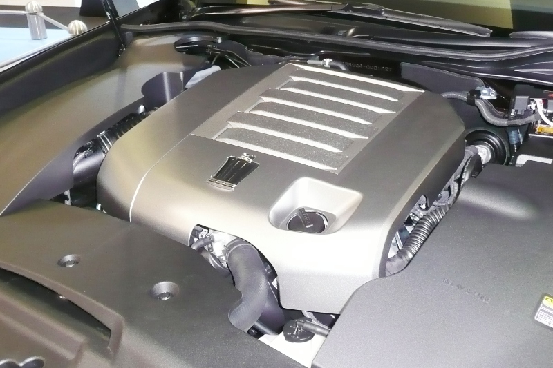
Dual VVT-i is also found in Toyota's new generation V6 engine, the 3.5-liter 2GR-FE first appearing on the 2005 Avalon. This engine can now be found on numerous Toyota and Lexus models. By adjusting the valve timing, engine start and stop occurs almost unnoticeably at minimum compression. In addition fast heating of the catalytic converter to its light-off temperature is possible thereby reducing hydrocarbon emissions considerably.

Toyota's UR engine V8 also uses this technology. Dual VVT-i was later introduced to Toyota's latest small 4-cylinder ZR engines found in compact vehicles such as the new Toyota Corolla and Scion xD and in larger 4-cylinder AR engines found in the Camry and RAV4.


In 1998, “Dual” VVT-i (adjusts both intake and exhaust camshafts) was first introduced in the RS200 Altezza’s 3S-GE engine. Dual VVT-i is also found in Toyota’s new generation V6 engine, the 3.5L 2GR-FE V6. This engine can be found in the Avalon, RAV4, and Camry in the US, the Aurion in Australia, and various models in Japan, including the Estima. Dual VVT-i is also used in the Toyota Corolla (1.6 dual VVT-i 124bhp).
Other Dual VVT-i engines include the 1.8L 2ZR-FE I4, used in Toyota’s next generation of compact vehicles such as the Scion XD. It is also used in the 2JZ-GE and 2JZ-GTE engines used in the Lexus IS300 and in the Toyota Supra. By adjusting the valve timing engine start and stop occurs virtually unnoticeably at minimum compression. In addition fast heating of the catalytic converter to its light-off temperature is possible thereby reducing hydrocarbon emissions considerably.


File:2GR-FSE.jpg